Dickenhardtstr. 67, 78054 Villingen-Schwenningen +49 (0) 7720-9770-0 info@romess.de

Select your language


Welcome to ROMESS!

Quality is when the customer comes back, not the product.”

With this motto, ROMESS-Rogg has been a successful market participant for over 50 years. Our spectrum of products and services for motor and utility vehicles comprises the following segments:Home-Bild.pngWe manufacture our equipment at our company headquarters in Villingen-Schwenningen, made in Germany. Our high-quality products are recommended by leading automobile manufacturers and valued by our long-standing customers for their reliability. In keeping with the words of founder and owner Werner Rogg: "Good servicing equipment allows our customers to perform necessary tasks faster and with more precision, thereby saving time and money."

Get to know us better

  50 Jahre ROMESS EN


              21242 Zeichen

  • Brake maintenance

    Brake maintenance

    High-quality, high-performance brake maintenance equipment - vintage or fitted with innovative RoTWIN technology for simultaneous brake ventilation, which significantly reduces the time required for every working procedure. Our equipment is recommended by leading automobile manufacturers!
  • Chassis measuring

    Chassis measuring

    The steering wheel balance for adjusting the “straight steering wheel” and for correcting tire tread wear, the inclinometer for adjusting toe, camber and castor as well as adjustment targets for adjusting various auxiliary systems, including night-vision and vehicle distance assistants. We offer you the right equipment!
  • Hydraulic units

    Hydraulic units

    Air pockets in the pipes for the clutch and switching systems impair the transmission of power, particularly when refilling after repairs. For this reason, it is important to fill these systems air pocket-free with the aid of high-quality equipment. Released and used by reputable utility vehicle manufacturers!
  • Engineering

    Engineering

    Leaks and noise sources can only be pinpointed with the naked eye or ear with difficulty - especially if they are coming from a place that is hard to access. Professionals use tools that allow them to avoid a lengthy and cost-intensive search. This is why the ultrasound leak detector USM 20128 was developed!

    Product Overview

    DOWNLOAD PRODUCT FLYER

    ver6

    The steering-wheel adjusting balance with electronic inclination RNW 2009 is fitted in the interior of the steering-wheel with a bearing device protected by utility patent with 4 usage bolts in the interior of the steering-wheel according to its diameter. Two strong springs ensure the firm hold of the steering-wheel balance in the steering wheel. The actual angle position of the steering wheel is displayed immediately. 

    Description
    The most effective tool with unprecedented accuracy for wheel alignment is the Romess steering wheel level RNW 2009 with electronic inclination gauge.

    The enhanced RNW 2009-S-F transmits the data via wireless to a Windows based wheel alignment computer.

    Technical Data
    •Angle measuring range: ±30° (optional ±80°)
    •Accuracy in the range 0° to 30°: ±0.1°
    •Automatic zero point
    •Inclination of steering-wheel max. 15°
    •Keys for measuring values storage and attenuation of the indication values
    •USB interface for data Transfer and for software-update
    •Nominal temperature range: +10° C to +45° C
    •Voltage supply: built in lithium-ionic-accus 910 mAh fast charging module.
    •Charging time about 4 hours., operating time with display background
      illumination about 20 hours

    Scope of delivery
    Device with case, USB-interface, charging device

    Order Numbers
    20090-10 (RNW 2009)
    20090-S-F (RNW 2009 with WLAN)

    Subject to error and modification

    DOWNLOAD PRODUCT FLYER

    When customers complain about vibrations while driving and/or irregularities in acceleration, the cause can be a deviation in the buckling-angle of the drive shaft from the set point. So far, there were only mechanical tools available to gauge the drive shaft.

    With the new electronic drive shaft angle gauge Romess 09935, the process is significantly easier and more accurate at the same time.

    ver4

    Structure and function
    The angle gauge 09935 consists of a hand held unit with graphics display and a sensor for measuring two levels. The measuring range is +/- 15°.

    To evaluate the alignment of the drivetrain, you must first measure the angles of the transmission, the prop-shafts and the rear axle differential.

    Different adaptations are needed for the sensor gauging the transmission and the differential. To measure the prop shafts, the measuring cones on the sensor can be held directly on the prop shaft. The result are shown on the display and saved by pressing the "Save" key. From two angles the unit calculates the difference which is relevant to the correct alignment of the drive shaft (difference ∠1∠2 = φ1; difference ∠2 ∠3 = φ2; difference
    ∠3 ∠4 = φ3).

    The sensor distinguishes between the x- and y-axis. To receive accurate results, the spiral cord on the sensor should always point toward the front of the vehicle.

    Characteristics
    - high measuring accuracy
    - easiest handling
    - power supplied by customary rechargeable batteries (4 x Mignon
      AA 1.2V/2100 mAh)
    - battery charger

    Technical data
    - CE certificate, Protection IP65
    - Power supply: 4.8V – 6V, 0.8W
    - Angle measuring range: +/- 15°, accuracy +/- 0.1°
    - Equipment: USB-interface and serial R232 for data transfer
    - Battery charger (12V/250mA)
    - Measurements (in mm): L x W x H: 450 x 380 x 120 (in the case)
      approx. 205 x 100 x 70 (without case)
    - Packing measurements (in mm): L x W x H: 455 x 400 x 120

    Scope of delivery
    Operating device with display, inclinometer, power supply, standard adapter (09606-50), carrying case.

    Accessories
    - data transfer and charging station with power supply, data cord (9 pole,
      1.2 m length) (09630-10)
    - interaxle-adapter (Type W163 M-class), MV-level measuring front axle
      (09606-60)
    - interaxle-adapter (Type W163 M-class), wheel caster measurement rear axle
      (09606-61)
    - adapter for W 414 (Vaneo) station wagon and panel truck (09606-62)

    Order Numbers
    09606-10 (230V/50Hz)
    09606-11 (110V/60Hz)

    Modifications and errors reserved.

    DOWNLOAD PRODUCT FLYER

    The combination gauge for both drive train alignment and inclination allows precise measurement of the drive train alignment as well as the ride height.

    Vehicle level (inclination) is used to determine the adjustment values for wheel camber, caster and toe. The drive train alignment is used when customers complain about vibrations while driving and / or irregularities in acceleration perhaps caused by a deviation in the buckling-angle of the drive shaft from the set point. So far, there were only mechanical tools available to gauge the drive shaft.

    ver3


    Structure and function
    The combination gauge 09905 consists of a hand held unit with graphic module and the sensor for measuring two levels. The measuring range is
    +/- 15°.

    You can select which measurement to gauge in the main menu. Whichever one you choose, the first steps will be shown on the display and the program LEDs light up to show the points of measure.

    To measure the lower transverse link of the front axle, the provided magnetic adaption plate 09606-50 is set in the designated recess to provide support for the sensor. Place the sensor with the points onto the adaption plate. The gauge results are shown on the display and saved by pressing the "Save" key. For gauging both the left and right side of the vehicle, ensure the spiral cord points toward the middle of the vehicle.

    No adapter is needed for measuring the rear axle shaft. The sensor points can be held directly onto the drive shaft (exception M Class W163; see accessories). Once again the spiral cord should point toward the middle of the vehicle. After saving all four measurements, the data can be transmitted to the wheel alignment computer either via interface (serial or USB) or by using the accessory unit "Data transfer and charging station 09630-10". The precise settings will be assigned automatically.

    Different adaptations are needed for the sensor gauging the transmission and the differential. To measure the prop shafts, the measuring cones on the sensor can be held directly on the prop shaft. The result are shown on the display and saved by pressing the "Save" key. From two angles the unit calculates the difference which is relevant to the correct alignment of the drive shaft (difference ∠1∠2 = φ1; difference ∠2 ∠3 = φ2; difference
    ∠3 ∠4 = φ3).

    The sensor distinguishes between the x- and y-axis. To receive accurate results, the spiral cord on the sensor should always point toward the front of the vehicle.

    Characteristics
    - High measuring accuracy
    - Easiest handling
    - Power supplied by customary rechargeable batteries (4x Mignon
      AA 1.2V/2100 mAh)
    - Battery charger

    Technical data
    - CE certificate, Protection IP65
    - Power supply: 4.8V – 6V, 0.8W
    - Angle measuring range: +/- 15°, accuracy +/- 0.1°
    - Equipment: USB-Interface and serial R232 for data transfer
    - Plug-in battery charger (12V/250mA)
    - Measurements (in mm): L x W x H: 450 x 380 x 120 (in the case)
      approx. 205 x 100 x 70 (without case)
    - Packing measurements (in mm): L x W x H: 455 x 400 x 120

    Scope of delivery
    Operating device with display, power supply, standard adapter for inclinometer 09606-50 and standard adapter set for propeller-shaft-buckling angle measurement 09935-25, carrying case.

    Accessories
    - Data transfer and charging station with power supply, data cord
      (9 pole, 1.2m length), order no. 09630-10 (230V), 09630-11 (110V)
    - Separate adaptations as a complete standard set, order no. 09935-25
    - Sensor support for adaptations, order no. 09935-20
    - Adaptation for transmission Ø 10 mm, order no. 09935-21
    - Adaptation for transmission Ø 15 mm, order no. 09935-22
    - Adaptation for transmission Ø 16 mm, order no. 09935-23
    - Adaptation for rear axle middle piece (Y-adaptation), order no. 09935-24
    - Adapter set complete for NCV2 (automatic transmission), order
      no. 20036-50 (not included in scope of delivery)

    Order No.
    09905-30 (230V/50Hz)
    09905-31 (110V/60Hz)

    Modifications and errors reserved.

    DOWNLOAD PRODUCT FLYER

    The data transfer and charging station serves as support for the inclinometer. On the bottom side of the inclinometer the contact connecting is simultaneously made for charging the accumulators and for the data transfer.

    ver2


    Description
    The charging of the accumulators is carried out in floating operation in order to avoid an overcharge of the accumulators. Herewith a continuous operation is granted. The durability of the accumulators is specified by the manufacturer. The data transfer station is electrically firmly linked with the vehicle gauging unit via connector power pack and data transfer line. When the inclinometer is placed onto the data transfer and charging station, the electrical contact is made to the vehicle gauging unit. The data transmission is effected automatically after actuating the key "Memory". After the data transmission has been carried out, it is indicated on the display of the inclinometer and at the same time the memorised data are deleted in the inclinometer. Only those data memorised via "Save" are transferred. If by error a measuring value has not been registered, i.e. not been memorised via "Save", it has to be remeasured once again at the measuring place, memorised via "Save" and be transferred again to the PC or the vehicle gauging unit by actuating the key "Memory".

    Indications
    •LED red luminous: Mains connection existing
    •LED yellow luminous: Contact connection between inclinometer and
      data transfer and charging station is in order
    •LED green blinking: Accumulator charging procedure
    •LED green luminous: Accumulator charging procedure finished
    •LED green off: Accumulator charged (no charging procedure required).

    Technical Data
    •Current consumption: approx. 1 Ampere
    •Working temperature: 0 – 70 degrees (drying chamber)
    •Interface: RS-232,19200 Baud
    •Data transfer line: D-Sub computer plug connector cable (9-pole, male)
    •Mains connection: Connector power pack
    •Dimensions (L x W x H) in mm: 120 x 200 x 120
    •Weight: approx. 2.0 kg

    Scope of delivery
    Data transfer and charging station with connector power pack and data transfer line, connecting cable 9-pole, length max. about 1.5 m.

    Order No.
    CM-09630-10 (230 volts)
    CM-09630-11 (110 volts); 
    CM-09630-12 (90 - 260 volts, international), optional

    Accessories
    Mains part plug, Input 230 V/50 Hz, Output 12 V AC/1,0 A (09630-50)
    Mains part plug, Input 110 V/60 HZ, Output 12 V AC/1.0 A (09630-60)

    Modifications and errors reserved.

    DOWNLOAD PRODUCT FLYER

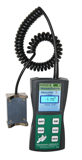
    Inclinometer RÖTES ROE 3018

    Application

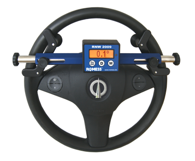
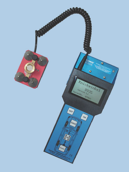
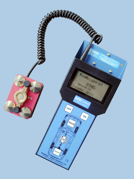
    The ROE 3018 inclinometer is used to measure the angular position of vehicle components. For example, the vehicle level is measured via the position of the transverse arm (Y-axle) at the front axle and the drive shaft at the rear axle (also called Y-axle). The values calculated can then be assigned to the adjustment values for camber, toe, and castor. The inclination of the X axle and the assigned Y-axle is measured. Should there be a deviation of more than +/-7° for the Y-axle, then the measured values must be disregarded to prevent measurement errors. The measured values are displayed in decimal degrees.

    Design and function

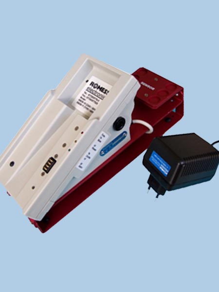
    The inclinometer ROE 3018 consists of a handheld device equipped with keyboard and graphic display as well as a sensor for measuring two planes, which is connected to the handheld device by means of a helical cable. The device is ready for immediate use since the sensor always remains at zero position (horizon). The device is self-adjusting (see the operating instructions), and consequently does not have to be sent in for periodic certification. The measuring range is +/- 30° on the X-axle and +/- 7° on the Y-axle. To measure the inclination of the lower transverse arm, the sensor must be held against an even surface (measuring point), for which an adapter plate may be required. Set up the sensor with the measuring tips, the measuring results will be shown on the display and stored by pressing the “save” key. You must make sure that the helical cable is always pointing toward the center of the vehicle, both when measuring the left side of the vehicle as well as when measuring the right side of the vehicle. This way, the sensor can distinguish between positive and negative values. No adapter is required to measure the rear axle shaft. Instead, the sensor is placed directly against the shaft with the prisma/V-block or, in the case of drive shafts with a diameter over 40 mm, with the measuring tips of the inclination sensor. Here, you must once again make sure that the cable is pointing toward the center of the vehicle. If all four measuring values are recorded, this can be displayed by pressing the “memory” button. A special version of the device is available with an additional protective cover (order number 3019 230V/50Hz, and/or 3119 110V/60Hz) that protects the device against shocks and minor damage, and prevents the device from slipping out of place.

    Neigungsmessgerät ROE 3018 klein

    Features

    • High measuring accuracy 
    • Easy handling 
    • Operation using commercially available batteries (3x Mignon AA 1,2 V/ approximately 1500 mAh)
    • Charging device (power adapter) (ONLY PERMITTED WHEN USING BATTERIES)

    Technical Data

    • CE certified, protection class IP43
    • Power supply: 3.6 V – 6V, 0.8W (3 x Mignon, 1.2V/ approximately 1500 mAh 
    • Angle measurement range: X +/- 30°, Y +/- 7°, accuracy: +/- approximately 0.1° 
    • Equipment: Mini USB interface data transmission (in preparation)
    • Plug-in power supply only for charging batteries (12V/250mA) 
    • Dimensions (L x W x H in mm): 450 x 380 x 120 (in the box), approximately 160 x 75 x 30 (without box) weight 2.1 kg 
    • Packing size (L x W x H in mm): 455 x 400 x 120, weight 2.5 kg 
    • Distribution package: Device in storage case, 3 batteries, plug-in power supply, operating instructions 
    • Accessories on request: Adapter 09606-50 standard adapter, 09606-60 for type W 163 (M-class), 09606-61 and 09606-65 for type W 163 (M-class), 09606-66 for type W 415 (Citan), 09606-70 for Maybach

    Note: Not yet released by Daimler AG.

    Order numbers

    EU - Without protection: 3018-10 
    EU - With protection: 3019-10   

    US - Without protection: 3018-11
    US - With protection: 3019-11

    UK - Without protection: 3018-12
    UK - With protection: 3019-12

    AUS - Without protection: 3018-13
    AUS - With protection: 3019-13

    More Articles …

    Page 1 of 2

    Current events

    news g1faf1a3fb 1920

    News, events, and dates by and with ROMESS. Here you will find upcoming trade fair dates, news regarding our company and its products as well as a great deal of information about ROMESS-Rogg, among other things. 

    Current news

    Media

    • Application video

      Application video

      Our tools at work
    • Romessage

      Romessage

      On this page, you can download our company magazine ROMESSAGE in PDF-format.
    • Media response

      Media response

      ROMESS in the specialized trade press.

      ROMESS-Rogg Apparate + Electronic GmbH + Co. KG
      Dickenhardtstr. 67
      78054 Villingen-Schwenningen
      Germany

      Telephone: +49 (0) 7720-9770-0
      Fax: +49 (0)7720-9770-25
      Email: info@romess.de